
Home > Network Rail > Bridges and Viaducts > Carnon Viaduct
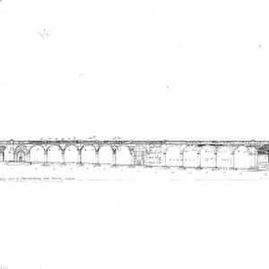
30500. Carnon Viaduct, 30500

![]()
Wall Art and Photo Gifts from Network Rail
30500. Carnon Viaduct, 30500
Network Rail - we run, look after and improve Britain's railway
Media ID 13454006
VISUAL DESCRIPTION
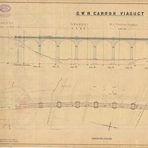
This image depicts an architectural blueprint of the G. W. R. Carnon Viaduct, as indicated by the title at the top center of the drawing. The blueprint is detailed and includes various views and cross-sections of different parts of the viaduct structure. The upper left corner features a side elevation view showing an arched section between two vertical supports or piers, with dimensions provided for reference. Below this are smaller diagrams detailing specific components such as voussoirs (wedge-shaped stones in arch construction), a plan view of a pier cap, and sections through a cornice detail. The central portion of the blueprint displays front elevations for five spans labeled Span No. 1 to Span No. 5, each with varying heights which suggests that they might be designed to accommodate different terrains or requirements along the viaduct's path. On both sides of these central drawings are additional details like enlarged plans and sections through piers, showcasing their robust construction meant to support significant weight and withstand environmental stresses. Throughout this technical document, one can observe annotations describing materials, measurements in feet and inches (indicative of imperial units used during its creation), references to other drawings ("See Drawing No. "), and notes on modifications or specifics about certain elements ("Extra Stone, " "Common Brick"). Overall, this historical engineering document provides insight into civil engineering practices from when it was created—likely during the late 19th or early 20th century—and represents meticulous planning required for constructing large-scale infrastructure projects like railway viaducts.
MADE IN THE USA
Safe Shipping with 30 Day Money Back Guarantee
FREE PERSONALISATION*
We are proud to offer a range of customisation features including Personalised Captions, Color Filters and Picture Zoom Tools
SECURE PAYMENTS
We happily accept a wide range of payment options so you can pay for the things you need in the way that is most convenient for you
* Options may vary by product and licensing agreement. Zoomed Pictures can be adjusted in the Cart.
![Leeds Joint Station - PRoposed re-arrangement of drainage in arches [ND]](/sq/229/leeds-joint-station-proposed-re-arrangement-9798282.jpg.webp)
![Cornwall Railway - Saltash Bridge General Drawing [c1858]](/sq/229/cornwall-railway-saltash-bridge-general-drawing-12596649.jpg.webp)
![G. W. R Royal Albert Bridge Saltash - General Drawing [N. D. ]](/sq/229/g-w-r-royal-albert-bridge-saltash-general-12596303.jpg.webp)
![Royal Albert Saltash Bridge - General Drawing [N. D. ]](/sq/229/royal-albert-saltash-bridge-general-drawing-n-12596299.jpg.webp)
![Saltash Bridge [N. D. ]](/sq/229/saltash-bridge-n-d-12596301.jpg.webp)
![G. N. R Derbyshire District - Radcliffe Viaduct Proposed Footway across River Trent [N. D]](/sq/229/g-n-r-derbyshire-district-radcliffe-viaduct-13850097.jpg.webp)